<< Chapter < Page Chapter >> Page >
I 0 Z = I 0 2 R 2 + ( I 0 X L I 0 X C ) 2 = I 0 R 2 + ( X L X C ) 2 . size 12{I rSub { size 8{0} } Z= sqrt {I rSub { size 8{0} rSup { size 8{2} } } R rSup { size 8{2} } + \( I rSub { size 8{0} } X rSub { size 8{L} } - I rSub { size 8{0} } X rSub { size 8{C} } \) rSup { size 8{2} } } =I rSub { size 8{0} } sqrt {R rSup { size 8{2} } + \( X rSub { size 8{L} } - X rSub { size 8{C} } \) rSup { size 8{2} } } } {}

I 0 size 12{I rSub { size 8{0} } } {} cancels to yield an expression for Z :

Z = R 2 + ( X L X C ) 2 , size 12{Z= sqrt {R rSup { size 8{2} } + \( X rSub { size 8{L} } - X rSub { size 8{C} } \) rSup { size 8{2} } } } {}

which is the impedance of an RLC series AC circuit. For circuits without a resistor, take R = 0 ; for those without an inductor, take X L = 0 size 12{X rSub { size 8{L} } =0} {} ; and for those without a capacitor, take X C = 0 size 12{X rSub { size 8{C} } =0} {} .

The figure shows graphs showing the relationships of the voltages in an RLC circuit to the current. It has five graphs on the left and two graphs on the right. The first graph on the right is for current I versus time t. Current is plotted along Y axis and time is along X axis. The curve is a smooth progressive sine wave. The second graph is on the right is for voltage V R versus time t. Voltage V R is plotted along Y axis and time is along X axis. The curve is a smooth progressive sine wave. The third graph is on the right is for voltage V L versus time t. Voltage V L is plotted along Y axis and time is along X axis. The curve is a smooth progressive cosine wave. The fourth graph is on the right is for voltage V C versus time t. Voltage V C is plotted along Y axis and time t is along X axis. The curve is a smooth progressive cosine wave starting from negative Y axis. The fifth graph shows the voltage V verses time t for the R L C circuit. Voltage V is plotted along Y axis and time t is along X axis. The curve is a smooth progressive sine wave starting from a point near to origin on negative X axis. The first and the fifth graphs are again shown on the right and their amplitudes and phases compared. The current graph is shown to have a lesser amplitude.
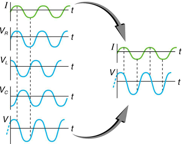
This graph shows the relationships of the voltages in an RLC circuit to the current. The voltages across the circuit elements add to equal the voltage of the source, which is seen to be out of phase with the current.

Calculating impedance and current

An RLC series circuit has a 40.0 Ω resistor, a 3.00 mH inductor, and a 5.00 μF capacitor. (a) Find the circuit’s impedance at 60.0 Hz and 10.0 kHz, noting that these frequencies and the values for L and C are the same as in [link] and [link] . (b) If the voltage source has V rms = 120 V size 12{V rSub { size 8{"rms"} } ="120"`V} {} , what is I rms size 12{I rSub { size 8{"rms"} } } {} at each frequency?

Strategy

For each frequency, we use Z = R 2 + ( X L X C ) 2 size 12{Z= sqrt {R rSup { size 8{2} } + \( X rSub { size 8{L} } - X rSub { size 8{C} } \) rSup { size 8{2} } } } {} to find the impedance and then Ohm’s law to find current. We can take advantage of the results of the previous two examples rather than calculate the reactances again.

Solution for (a)

At 60.0 Hz, the values of the reactances were found in [link] to be X L = 1 . 13 Ω size 12{X rSub { size 8{L} } =1 "." "13" %OMEGA } {} and in [link] to be X C = 531 Ω size 12{X rSub { size 8{C} } ="531 " %OMEGA } {} . Entering these and the given 40.0 Ω for resistance into Z = R 2 + ( X L X C ) 2 size 12{Z= sqrt {R rSup { size 8{2} } + \( X rSub { size 8{L} } - X rSub { size 8{C} } \) rSup { size 8{2} } } } {} yields

Z = R 2 + ( X L X C ) 2 = ( 40 . 0 Ω ) 2 + ( 1 . 13 Ω 531 Ω ) 2 = 531 Ω  at 60 . 0 Hz . alignl { stack { size 12{Z= sqrt {R rSup { size 8{2} } + \( X rSub { size 8{L} } - X rSub { size 8{C} } \) rSup { size 8{2} } } } {} #" "= sqrt { \( "40" "." 0` %OMEGA \) rSup { size 8{2} } + \( 1 "." "13" %OMEGA - "531" %OMEGA \) rSup { size 8{2} } } {} # " "="531" %OMEGA " at 60" "." "0 Hz" {}} } {}

Similarly, at 10.0 kHz, X L = 188 Ω size 12{X rSub { size 8{L} } ="188" %OMEGA } {} and X C = 3 . 18 Ω size 12{X rSub { size 8{C} } =3 "." "18" %OMEGA } {} , so that

Z = ( 40 . 0 Ω ) 2 + ( 188 Ω 3 . 18 Ω ) 2 = 190 Ω  at 10 . 0 kHz. alignl { stack { size 12{Z= sqrt { \( "40" "." 0` %OMEGA \) rSup { size 8{2} } + \( "188" %OMEGA - 3 "." "18" %OMEGA \) rSup { size 8{2} } } } {} #" "="190" %OMEGA " at 10" "." "0 kHz" {} } } {}

Discussion for (a)

In both cases, the result is nearly the same as the largest value, and the impedance is definitely not the sum of the individual values. It is clear that X L size 12{X rSub { size 8{L} } } {} dominates at high frequency and X C size 12{X rSub { size 8{C} } } {} dominates at low frequency.

Solution for (b)

The current I rms size 12{I rSub { size 8{"rms"} } } {} can be found using the AC version of Ohm’s law in Equation I rms = V rms / Z size 12{I rSub { size 8{"rms"} } =V rSub { size 8{"rms"} } /Z} {} :

I rms = V rms Z = 120 V 531 Ω = 0 . 226 A size 12{I rSub { size 8{"rms"} } = { {V rSub { size 8{"rms"} } } over {Z} } = { {"120"" V"} over {"531 " %OMEGA } } =0 "." "226"" A"} {} at 60.0 Hz

Finally, at 10.0 kHz, we find

I rms = V rms Z = 120 V 190 Ω = 0 . 633 A size 12{I rSub { size 8{"rms"} } = { {V rSub { size 8{"rms"} } } over {Z} } = { {"120"" V"} over {"190 " %OMEGA } } =0 "." "633"" A"} {} at 10.0 kHz

Discussion for (a)

The current at 60.0 Hz is the same (to three digits) as found for the capacitor alone in [link] . The capacitor dominates at low frequency. The current at 10.0 kHz is only slightly different from that found for the inductor alone in [link] . The inductor dominates at high frequency.

Got questions? Get instant answers now!

Resonance in RLC Series ac circuits

How does an RLC circuit behave as a function of the frequency of the driving voltage source? Combining Ohm’s law, I rms = V rms / Z size 12{I rSub { size 8{"rms"} } =V rSub { size 8{"rms"} } /Z} {} , and the expression for impedance Z from Z = R 2 + ( X L X C ) 2 size 12{Z= sqrt {R rSup { size 8{2} } + \( X rSub { size 8{L} } - X rSub { size 8{C} } \) rSup { size 8{2} } } } {} gives

I rms = V rms R 2 + ( X L X C ) 2 . size 12{I rSub { size 8{"rms"} } = { {V rSub { size 8{"rms"} } } over { sqrt {R rSup { size 8{2} } + \( X rSub { size 8{L} } - X rSub { size 8{C} } \) rSup { size 8{2} } } } } } {}

The reactances vary with frequency, with X L size 12{X rSub { size 8{L} } } {} large at high frequencies and X C size 12{X rSub { size 8{C} } } {} large at low frequencies, as we have seen in three previous examples. At some intermediate frequency f 0 size 12{f rSub { size 8{0} } } {} , the reactances will be equal and cancel, giving Z = R size 12{Z=R} {} —this is a minimum value for impedance, and a maximum value for I rms size 12{I rSub { size 8{"rms"} } } {} results. We can get an expression for f 0 size 12{f rSub { size 8{0} } } {} by taking

X L = X C . size 12{X rSub { size 8{L} } =X rSub { size 8{C} } } {}

Substituting the definitions of X L size 12{X rSub { size 8{L} } } {} and X C size 12{X rSub { size 8{C} } } {} ,

2 πf 0 L = 1 2 πf 0 C . size 12{2πf rSub { size 8{0} } L= { {1} over {2πf rSub { size 8{0} } C} } } {}

Solving this expression for f 0 size 12{f rSub { size 8{0} } } {} yields

f 0 = 1 LC , size 12{f rSub { size 8{0} } = { {1} over {2π sqrt { ital "LC"} } } } {}

where f 0 size 12{f rSub { size 8{0} } } {} is the resonant frequency    of an RLC series circuit. This is also the natural frequency at which the circuit would oscillate if not driven by the voltage source. At f 0 size 12{f rSub { size 8{0} } } {} , the effects of the inductor and capacitor cancel, so that Z = R size 12{Z=R} {} , and I rms size 12{I rSub { size 8{"rms"} } } {} is a maximum.

Questions & Answers

Ayele, K., 2003. Introductory Economics, 3rd ed., Addis Ababa.
Widad Reply
can you send the book attached ?
Ariel
?
Ariel
What is economics
Widad Reply
the study of how humans make choices under conditions of scarcity
AI-Robot
U(x,y) = (x×y)1/2 find mu of x for y
Desalegn Reply
U(x,y) = (x×y)1/2 find mu of x for y
Desalegn
what is ecnomics
Jan Reply
this is the study of how the society manages it's scarce resources
Belonwu
what is macroeconomic
John Reply
macroeconomic is the branch of economics which studies actions, scale, activities and behaviour of the aggregate economy as a whole.
husaini
etc
husaini
difference between firm and industry
husaini Reply
what's the difference between a firm and an industry
Abdul
firm is the unit which transform inputs to output where as industry contain combination of firms with similar production 😅😅
Abdulraufu
Suppose the demand function that a firm faces shifted from Qd  120 3P to Qd  90  3P and the supply function has shifted from QS  20  2P to QS 10  2P . a) Find the effect of this change on price and quantity. b) Which of the changes in demand and supply is higher?
Toofiq Reply
explain standard reason why economic is a science
innocent Reply
factors influencing supply
Petrus Reply
what is economic.
Milan Reply
scares means__________________ends resources. unlimited
Jan
economics is a science that studies human behaviour as a relationship b/w ends and scares means which have alternative uses
Jan
calculate the profit maximizing for demand and supply
Zarshad Reply
Why qualify 28 supplies
Milan
what are explicit costs
Nomsa Reply
out-of-pocket costs for a firm, for example, payments for wages and salaries, rent, or materials
AI-Robot
concepts of supply in microeconomics
David Reply
economic overview notes
Amahle Reply
identify a demand and a supply curve
Salome Reply
i don't know
Parul
there's a difference
Aryan
Demand curve shows that how supply and others conditions affect on demand of a particular thing and what percent demand increase whith increase of supply of goods
Israr
Hi Sir please how do u calculate Cross elastic demand and income elastic demand?
Abari
Got questions? Join the online conversation and get instant answers!
Jobilize.com Reply
Practice Key Terms 4

Get Jobilize Job Search Mobile App in your pocket Now!

Get it on Google Play Download on the App Store Now


Source:  OpenStax, College physics. OpenStax CNX. Jul 27, 2015 Download for free at http://legacy.cnx.org/content/col11406/1.9
Google Play and the Google Play logo are trademarks of Google Inc.

Notification Switch

Would you like to follow the 'College physics' conversation and receive update notifications?

Ask