<< Chapter < Page Chapter >> Page >

A pure LC circuit with negligible resistance oscillates at f 0 size 12{f rSub { size 8{0} } } {} , the same resonant frequency as an RLC circuit. It can serve as a frequency standard or clock circuit—for example, in a digital wristwatch. With a very small resistance, only a very small energy input is necessary to maintain the oscillations. The circuit is analogous to a car with no shock absorbers. Once it starts oscillating, it continues at its natural frequency for some time. 
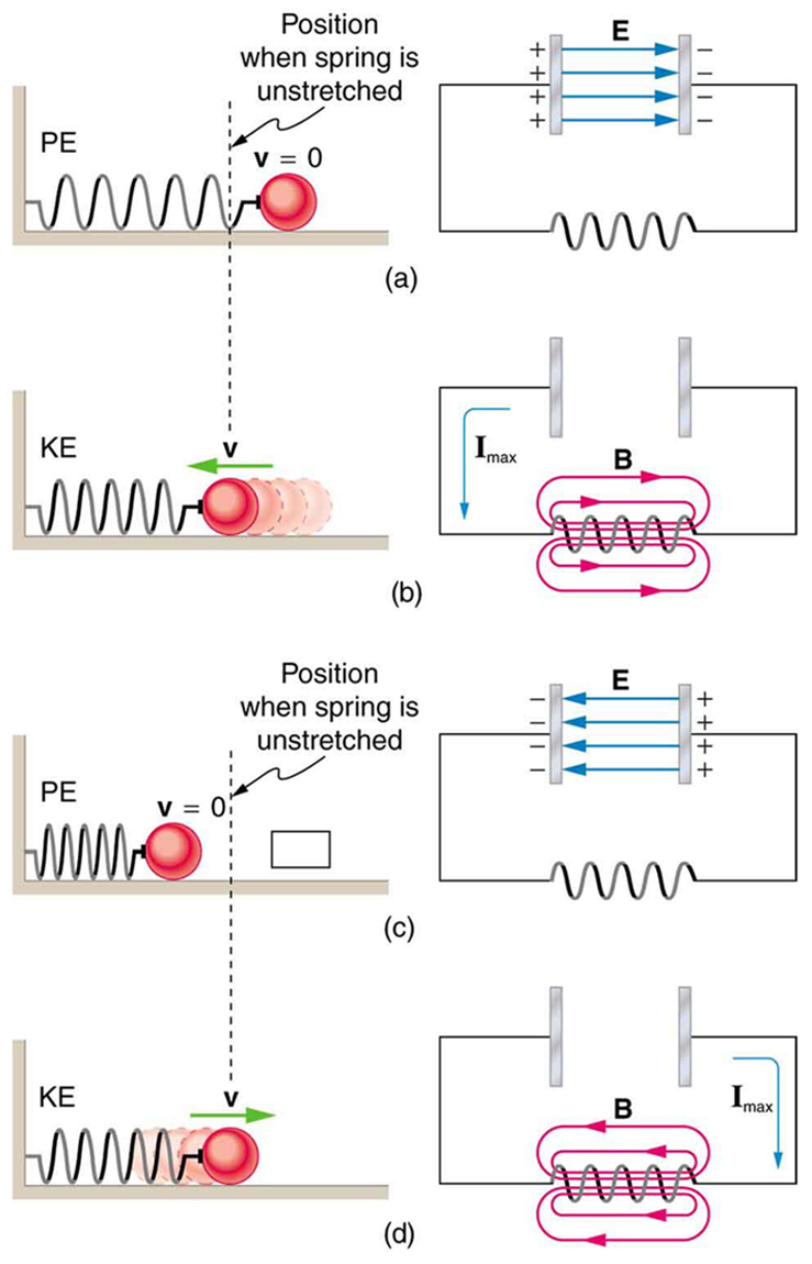
[link] shows the analogy between an LC circuit and a mass on a spring.

The figure describes four stages of an L C oscillation circuit compared to a mass oscillating on a spring. Part a of the figure shows a mass attached to a horizontal spring. The spring is attached to a fixed support on the left. The mass is at rest as shown by velocity v equals zero. The energy of the spring is shown as potential energy. This is compared with a circuit containing a capacitor C and inductor L connected together. The energy is shown as stored in the electric field E of the capacitor between the plates. One plate is shown to have a negative polarity and other plate is shown to have a positive polarity. Part b of the figure shows a mass attached to a horizontal spring which is attached to a fixed support on the left. The mass is shown to move horizontal toward the fixed support with velocity v. The energy here is stored as the kinetic energy of the spring. This is compared with a circuit containing a capacitor C and inductor L connected together. A current is shown in the circuit and energy is stored as magnetic field B in the inductor. Part c of the figure shows a mass attached to a horizontal spring which is attached to a fixed support on the left. The spring is shown as not stretched and the energy is shown as potential energy of the spring. The mass is show to have displaced toward left. This is compared with a circuit containing a capacitor C and inductor L connected together. The energy is shown as stored in the electric field E of the capacitor between the plates. One plate is shown to have a negative polarity and other plate is shown to have a positive polarity. But the polarities are reverse of the first case in part a. Part d of the figure shows a mass attached to a horizontal spring which is attached to a fixed support on the left. The mass is shown to move toward right with velocity v. the energy of the spring is kinetic energy. This is compared with a circuit containing a capacitor C and inductor L connected together. A current is shown in the circuit opposite to that in part b and energy is stored as magnetic field B in the inductor.
An LC circuit is analogous to a mass oscillating on a spring with no friction and no driving force. Energy moves back and forth between the inductor and capacitor, just as it moves from kinetic to potential in the mass-spring system.

Phet explorations: circuit construction kit (ac+dc), virtual lab

Build circuits with capacitors, inductors, resistors and AC or DC voltage sources, and inspect them using lab instruments such as voltmeters and ammeters.

Circuit Construction Kit (AC+DC), Virtual Lab

Section summary

  • The AC analogy to resistance is impedance Z , the combined effect of resistors, inductors, and capacitors, defined by the AC version of Ohm’s law:
    I 0 = V 0 Z or I rms = V rms Z , size 12{I rSub { size 8{0} } = { {V rSub { size 8{0} } } over {Z} } " or "I rSub { size 8{ ital "rms"} } = { {V rSub { size 8{ ital "rms"} } } over {Z} } ,} {}
    where I 0 size 12{I rSub { size 8{0} } } {} is the peak current and V 0 size 12{V rSub { size 8{0} } } {} is the peak source voltage.
  • Impedance has units of ohms and is given by Z = R 2 + ( X L X C ) 2 size 12{Z= sqrt {R rSup { size 8{2} } + \( X rSub { size 8{L} } - X rSub { size 8{C} } \) rSup { size 8{2} } } } {} .
  • The resonant frequency f 0 size 12{f rSub { size 8{0} } } {} , at which X L = X C size 12{X rSub { size 8{L} } =X rSub { size 8{C} } } {} , is
    f 0 = 1 LC . size 12{f rSub { size 8{0} } = { {1} over {2π sqrt { ital "LC"} } } } {}
  • In an AC circuit, there is a phase angle ϕ size 12{ϕ} {} between source voltage V size 12{V} {} and the current I size 12{I} {} , which can be found from
    cos ϕ = R Z , size 12{"cos"ϕ= { {R} over {Z} } } {}
  • ϕ = size 12{ϕ=0 rSup { size 8{ circ } } } {} for a purely resistive circuit or an RLC circuit at resonance.
  • The average power delivered to an RLC circuit is affected by the phase angle and is given by
    P ave = I rms V rms cos ϕ , size 12{P rSub { size 8{"ave"} } =I rSub { size 8{"rms"} } V rSub { size 8{"rms"} } "cos"ϕ} {}
    cos ϕ size 12{"cos"ϕ} {} is called the power factor, which ranges from 0 to 1.

Conceptual questions

Does the resonant frequency of an AC circuit depend on the peak voltage of the AC source? Explain why or why not.

Got questions? Get instant answers now!

Suppose you have a motor with a power factor significantly less than 1. Explain why it would be better to improve the power factor as a method of improving the motor’s output, rather than to increase the voltage input.

Got questions? Get instant answers now!

Problems&Exercises

An RL circuit consists of a 40.0 Ω resistor and a 3.00 mH inductor. (a) Find its impedance Z at 60.0 Hz and 10.0 kHz. (b) Compare these values of Z with those found in [link] in which there was also a capacitor.

(a) 40.02 Ω at 60.0 Hz, 193 Ω at 10.0 kHz

(b) At 60 Hz, with a capacitor, Z=531 Ω , over 13 times as high as without the capacitor. The capacitor makes a large difference at low frequencies. At 10 kHz, with a capacitor Z=190 Ω , about the same as without the capacitor. The capacitor has a smaller effect at high frequencies.

Got questions? Get instant answers now!

An RC circuit consists of a 40.0 Ω resistor and a 5.00 μF capacitor. (a) Find its impedance at 60.0 Hz and 10.0 kHz. (b) Compare these values of Z with those found in [link] , in which there was also an inductor.

Got questions? Get instant answers now!

An LC circuit consists of a 3 . 00 mH size 12{3 "." "00" μH} {} inductor and a 5 . 00 μF size 12{5 "." "00" μF} {} capacitor. (a) Find its impedance at 60.0 Hz and 10.0 kHz. (b) Compare these values of Z size 12{Z} {} with those found in [link] in which there was also a resistor.

(a) 529 Ω at 60.0 Hz, 185 Ω at 10.0 kHz

(b) These values are close to those obtained in [link] because at low frequency the capacitor dominates and at high frequency the inductor dominates. So in both cases the resistor makes little contribution to the total impedance.

Got questions? Get instant answers now!

What is the resonant frequency of a 0.500 mH inductor connected to a 40.0 μF capacitor?

Got questions? Get instant answers now!

To receive AM radio, you want an RLC circuit that can be made to resonate at any frequency between 500 and 1650 kHz. This is accomplished with a fixed 1.00 μH inductor connected to a variable capacitor. What range of capacitance is needed?

9.30 nF to 101 nF

Got questions? Get instant answers now!

Suppose you have a supply of inductors ranging from 1.00 nH to 10.0 H, and capacitors ranging from 1.00 pF to 0.100 F. What is the range of resonant frequencies that can be achieved from combinations of a single inductor and a single capacitor?

Got questions? Get instant answers now!

What capacitance do you need to produce a resonant frequency of 1.00 GHz, when using an 8.00 nH inductor?

3.17 pF

Got questions? Get instant answers now!

What inductance do you need to produce a resonant frequency of 60.0 Hz, when using a 2.00 μF capacitor?

Got questions? Get instant answers now!

The lowest frequency in the FM radio band is 88.0 MHz. (a) What inductance is needed to produce this resonant frequency if it is connected to a 2.50 pF capacitor? (b) The capacitor is variable, to allow the resonant frequency to be adjusted to as high as 108 MHz. What must the capacitance be at this frequency?

(a) 1.31 μH

(b) 1.66 pF

Got questions? Get instant answers now!

An RLC series circuit has a 2.50 Ω resistor, a 100 μH inductor, and an 80.0 μF capacitor.(a) Find the circuit’s impedance at 120 Hz. (b) Find the circuit’s impedance at 5.00 kHz. (c) If the voltage source has V rms = 5 . 60 V size 12{V rSub { size 8{"rms"} } =5 "." "60"`V} {} , what is I rms size 12{I rSub { size 8{"rms"} } } {} at each frequency? (d) What is the resonant frequency of the circuit? (e) What is I rms size 12{I rSub { size 8{"rms"} } } {} at resonance?

Got questions? Get instant answers now!

An RLC series circuit has a 1.00 kΩ resistor, a 150 μH inductor, and a 25.0 nF capacitor. (a) Find the circuit’s impedance at 500 Hz. (b) Find the circuit’s impedance at 7.50 kHz. (c) If the voltage source has V rms = 408 V size 12{V rSub { size 8{"rms"} } ="408"`V} {} , what is I rms size 12{I rSub { size 8{"rms"} } } {} at each frequency? (d) What is the resonant frequency of the circuit? (e) What is I rms size 12{I rSub { size 8{"rms"} } } {} at resonance?

(a) 12.8 kΩ

(b) 1.31 kΩ

(c) 31.9 mA at 500 Hz, 312 mA at 7.50 kHz

(d) 82.2 kHz

(e) 0.408 A

Got questions? Get instant answers now!

An RLC series circuit has a 2.50 Ω resistor, a 100 μH inductor, and an 80.0 μF capacitor. (a) Find the power factor at f = 120 Hz . (b) What is the phase angle at 120 Hz? (c) What is the average power at 120 Hz? (d) Find the average power at the circuit’s resonant frequency.

Got questions? Get instant answers now!

An RLC series circuit has a 1.00 kΩ resistor, a 150 μH inductor, and a 25.0 nF capacitor. (a) Find the power factor at f = 7.50 Hz . (b) What is the phase angle at this frequency? (c) What is the average power at this frequency? (d) Find the average power at the circuit’s resonant frequency.

(a) 0.159

(b) 80.9º

(c) 26.4 W

(d) 166 W

Got questions? Get instant answers now!

An RLC series circuit has a 200 Ω resistor and a 25.0 mH inductor. At 8000 Hz, the phase angle is 45.0º . (a) What is the impedance? (b) Find the circuit’s capacitance. (c) If V rms = 408 V size 12{V rSub { size 8{"rms"} } ="408"`V} {} is applied, what is the average power supplied?

Got questions? Get instant answers now!

Referring to [link] , find the average power at 10.0 kHz.

16.0 W

Got questions? Get instant answers now!

Questions & Answers

A golfer on a fairway is 70 m away from the green, which sits below the level of the fairway by 20 m. If the golfer hits the ball at an angle of 40° with an initial speed of 20 m/s, how close to the green does she come?
Aislinn Reply
cm
tijani
what is titration
John Reply
what is physics
Siyaka Reply
A mouse of mass 200 g falls 100 m down a vertical mine shaft and lands at the bottom with a speed of 8.0 m/s. During its fall, how much work is done on the mouse by air resistance
Jude Reply
Can you compute that for me. Ty
Jude
what is the dimension formula of energy?
David Reply
what is viscosity?
David
what is inorganic
emma Reply
what is chemistry
Youesf Reply
what is inorganic
emma
Chemistry is a branch of science that deals with the study of matter,it composition,it structure and the changes it undergoes
Adjei
please, I'm a physics student and I need help in physics
Adjanou
chemistry could also be understood like the sexual attraction/repulsion of the male and female elements. the reaction varies depending on the energy differences of each given gender. + masculine -female.
Pedro
A ball is thrown straight up.it passes a 2.0m high window 7.50 m off the ground on it path up and takes 1.30 s to go past the window.what was the ball initial velocity
Krampah Reply
2. A sled plus passenger with total mass 50 kg is pulled 20 m across the snow (0.20) at constant velocity by a force directed 25° above the horizontal. Calculate (a) the work of the applied force, (b) the work of friction, and (c) the total work.
Sahid Reply
you have been hired as an espert witness in a court case involving an automobile accident. the accident involved car A of mass 1500kg which crashed into stationary car B of mass 1100kg. the driver of car A applied his brakes 15 m before he skidded and crashed into car B. after the collision, car A s
Samuel Reply
can someone explain to me, an ignorant high school student, why the trend of the graph doesn't follow the fact that the higher frequency a sound wave is, the more power it is, hence, making me think the phons output would follow this general trend?
Joseph Reply
Nevermind i just realied that the graph is the phons output for a person with normal hearing and not just the phons output of the sound waves power, I should read the entire thing next time
Joseph
Follow up question, does anyone know where I can find a graph that accuretly depicts the actual relative "power" output of sound over its frequency instead of just humans hearing
Joseph
"Generation of electrical energy from sound energy | IEEE Conference Publication | IEEE Xplore" ***ieeexplore.ieee.org/document/7150687?reload=true
Ryan
what's motion
Maurice Reply
what are the types of wave
Maurice
answer
Magreth
progressive wave
Magreth
hello friend how are you
Muhammad Reply
fine, how about you?
Mohammed
hi
Mujahid
A string is 3.00 m long with a mass of 5.00 g. The string is held taut with a tension of 500.00 N applied to the string. A pulse is sent down the string. How long does it take the pulse to travel the 3.00 m of the string?
yasuo Reply
Who can show me the full solution in this problem?
Reofrir Reply
Got questions? Join the online conversation and get instant answers!
Jobilize.com Reply
Practice Key Terms 4

Get Jobilize Job Search Mobile App in your pocket Now!

Get it on Google Play Download on the App Store Now


Source:  OpenStax, College physics. OpenStax CNX. Jul 27, 2015 Download for free at http://legacy.cnx.org/content/col11406/1.9
Google Play and the Google Play logo are trademarks of Google Inc.

Notification Switch

Would you like to follow the 'College physics' conversation and receive update notifications?

Ask