| << Chapter < Page | Chapter >> Page > |
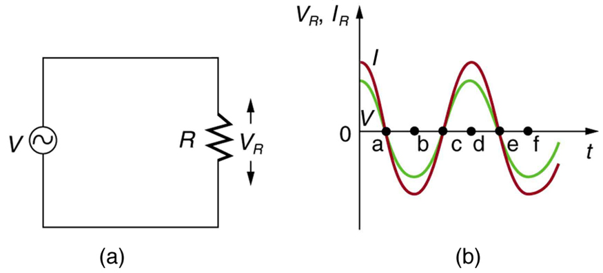
Just as a reminder, consider [link] , which shows an AC voltage applied to a resistor and a graph of voltage and current versus time. The voltage and current are exactly in phase in a resistor. There is no frequency dependence to the behavior of plain resistance in a circuit:

When a sinusoidal voltage is applied to a resistor, the voltage is exactly in phase with the current—they have a phase angle.
Presbycusis is a hearing loss due to age that progressively affects higher frequencies. A hearing aid amplifier is designed to amplify all frequencies equally. To adjust its output for presbycusis, would you put a capacitor in series or parallel with the hearing aid’s speaker? Explain.
Would you use a large inductance or a large capacitance in series with a system to filter out low frequencies, such as the 100 Hz hum in a sound system? Explain.
High-frequency noise in AC power can damage computers. Does the plug-in unit designed to prevent this damage use a large inductance or a large capacitance (in series with the computer) to filter out such high frequencies? Explain.
Does inductance depend on current, frequency, or both? What about inductive reactance?
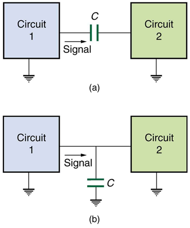
Explain why the capacitor in [link] (a) acts as a low-frequency filter between the two circuits, whereas that in [link] (b) acts as a high-frequency filter.

If the capacitors in [link] are replaced by inductors, which acts as a low-frequency filter and which as a high-frequency filter?
At what frequency will a 30.0 mH inductor have a reactance of ?
531 Hz
What value of inductance should be used if a reactance is needed at a frequency of 500 Hz?
What capacitance should be used to produce a reactance at 60.0 Hz?
1.33 nF
At what frequency will an 80.0 mF capacitor have a reactance of ?
(a) Find the current through a 0.500 H inductor connected to a 60.0 Hz, 480 V AC source. (b) What would the current be at 100 kHz?
(a) 2.55 A
(b) 1.53 mA
(a) What current flows when a 60.0 Hz, 480 V AC source is connected to a capacitor? (b) What would the current be at 25.0 kHz?
A 20.0 kHz, 16.0 V source connected to an inductor produces a 2.00 A current. What is the inductance?
A 20.0 Hz, 16.0 V source produces a 2.00 mA current when connected to a capacitor. What is the capacitance?
(a) An inductor designed to filter high-frequency noise from power supplied to a personal computer is placed in series with the computer. What minimum inductance should it have to produce a reactance for 15.0 kHz noise? (b) What is its reactance at 60.0 Hz?
(a) 21.2 mH
(b)
The capacitor in [link] (a) is designed to filter low-frequency signals, impeding their transmission between circuits. (a) What capacitance is needed to produce a reactance at a frequency of 120 Hz? (b) What would its reactance be at 1.00 MHz? (c) Discuss the implications of your answers to (a) and (b).
The capacitor in [link] (b) will filter high-frequency signals by shorting them to earth/ground. (a) What capacitance is needed to produce a reactance of for a 5.00 kHz signal? (b) What would its reactance be at 3.00 Hz? (c) Discuss the implications of your answers to (a) and (b).
(a) 3.18 mF
(b)
Unreasonable Results
In a recording of voltages due to brain activity (an EEG), a 10.0 mV signal with a 0.500 Hz frequency is applied to a capacitor, producing a current of 100 mA. Resistance is negligible. (a) What is the capacitance? (b) What is unreasonable about this result? (c) Which assumption or premise is responsible?
Construct Your Own Problem
Consider the use of an inductor in series with a computer operating on 60 Hz electricity. Construct a problem in which you calculate the relative reduction in voltage of incoming high frequency noise compared to 60 Hz voltage. Among the things to consider are the acceptable series reactance of the inductor for 60 Hz power and the likely frequencies of noise coming through the power lines.

Notification Switch
Would you like to follow the 'College physics for ap® courses' conversation and receive update notifications?