<< Chapter < Page Chapter >> Page >

Learning objectives

By the end of this section, you will be able to:

  • Describe the effects of the magnetic force between two conductors.
  • Calculate the force between two parallel conductors.

The information presented in this section supports the following AP® learning objectives and science practices:

  • 2.D.2.1 The student is able to create a verbal or visual representation of a magnetic field around a long straight wire or a pair of parallel wires. (S.P. 1.1)
  • 3.C.3.1 The student is able to use right-hand rules to analyze a situation involving a current-carrying conductor and a moving electrically charged object to determine the direction of the magnetic force exerted on the charged object due to the magnetic field created by the current-carrying conductor. (S.P. 1.4)

You might expect that there are significant forces between current-carrying wires, since ordinary currents produce significant magnetic fields and these fields exert significant forces on ordinary currents. But you might not expect that the force between wires is used to define the ampere. It might also surprise you to learn that this force has something to do with why large circuit breakers burn up when they attempt to interrupt large currents.

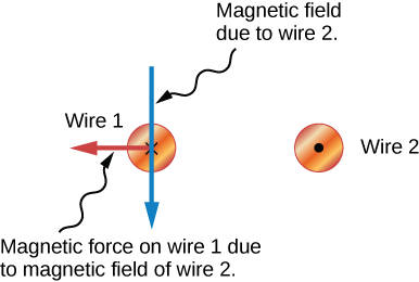
The force between two long straight and parallel conductors separated by a distance r size 12{r} {} can be found by applying what we have developed in preceding sections. [link] shows the wires, their currents, the fields they create, and the subsequent forces they exert on one another. Let us consider the field produced by wire 1 and the force it exerts on wire 2 (call the force F 2 size 12{F rSub { size 8{2} } } {} ). The field due to I 1 size 12{I rSub { size 8{1} } } {} at a distance r size 12{r} {} is given to be

B 1 = μ 0 I 1 2 πr . size 12{B rSub { size 8{1} } = { {μ rSub { size 8{0} } I rSub { size 8{1} } } over {2πr} } "." } {}
Figure a shows two parallel wires, both with currents going up. The magnetic field lines of the first wire are shown as concentric circles centered on wire 1 and in a plane perpendicular to the wires. The magnetic field is in the counter clockwise direction as viewed from above. Figure b shows a view from above and shows the current-carrying wires as two dots. Around wire one is a circle that represents a magnetic field line due to that wire. The magnetic field passes directly through wire two. The magnetic field is in the counter clockwise direction. The force on wire two is to the left, toward wire one.
(a) The magnetic field produced by a long straight conductor is perpendicular to a parallel conductor, as indicated by RHR-2. (b) A view from above of the two wires shown in (a), with one magnetic field line shown for each wire. RHR-1 shows that the force between the parallel conductors is attractive when the currents are in the same direction. A similar analysis shows that the force is repulsive between currents in opposite directions.

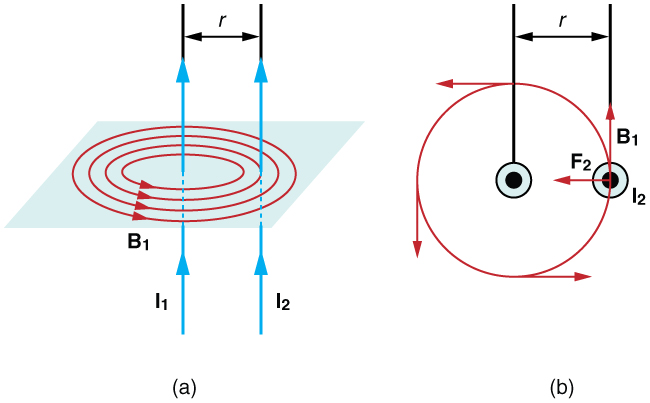
This field is uniform along wire 2 and perpendicular to it, and so the force F 2 size 12{F rSub { size 8{2} } } {} it exerts on wire 2 is given by F = IlB sin θ size 12{F= ital "IlB""sin"θ} {} with sin θ = 1 size 12{"sin"θ=1} {} :

F 2 = I 2 lB 1 . size 12{F rSub { size 8{2} } =I rSub { size 8{2} } ital "lB" rSub { size 8{1} } } {}

By Newton’s third law, the forces on the wires are equal in magnitude, and so we just write F size 12{F} {} for the magnitude of F 2 size 12{F rSub { size 8{2} } } {} . (Note that F 1 = F 2 size 12{F rSub { size 8{1} } = - F rSub { size 8{2} } } {} .) Since the wires are very long, it is convenient to think in terms of F / l size 12{F/l} {} , the force per unit length. Substituting the expression for B 1 size 12{B rSub { size 8{1} } } {} into the last equation and rearranging terms gives

F l = μ 0 I 1 I 2 2 πr . size 12{ { {F} over {l} } = { {μ rSub { size 8{0} } I rSub { size 8{1} } I rSub { size 8{2} } } over {2πr} } "." } {}

F / l size 12{F/l} {} is the force per unit length between two parallel currents I 1 size 12{I rSub { size 8{1} } } {} and I 2 size 12{I rSub { size 8{2} } } {} separated by a distance r size 12{r} {} . The force is attractive if the currents are in the same direction and repulsive if they are in opposite directions.

Making connections: field canceling

For two parallel wires, the fields will tend to cancel out in the area between the wires.

There are two small circles with dots in the center representing wires going in the same direction. Each circle has three progressively larger circles with arrows pointing in counter-clockwise positions representing the magnetic fields going in the same direction. The center circles are close enough that the first outer circle is between the two circles and the second outer circle bisects the other’s center circle.
Two parallel wires have currents pointing in the same direction, out of the page. The direction of the magnetic fields induced by each wire is shown.

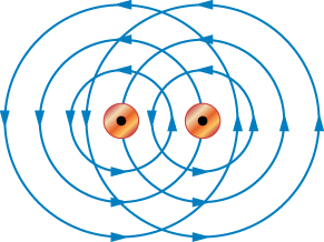
Note that the magnetic influence of the wire on the left-hand side extends beyond the wire on the right-hand side. To the right of both wires, the total magnetic field is directed toward the top of the page and is the result of the sum of the fields of both wires. Obviously, the closer wire has a greater effect on the overall magnetic field, but the more distant wire also contributes. One wire cannot block the magnetic field of another wire any more than a massive stone floor beneath you can block the gravitational field of the Earth.

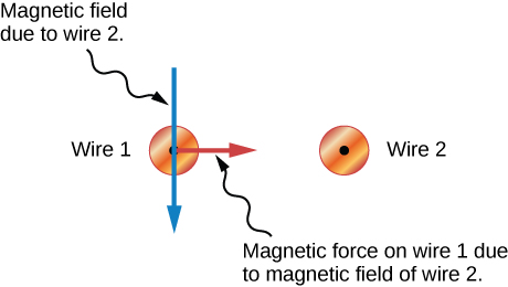
Parallel wires with currents in the same direction attract, as you can see if we isolate the magnetic field lines of wire 2 influencing the current in wire 1. Right-hand rule 1 tells us the direction of the resulting magnetic force.

The two small circles with dots representing wires are shown again in this diagram without the circles representing the magnetic fields. A blue arrow pointing down going through wire 1 is labeled Magnetic field due to wire 2. A red line from the center of wire 1 pointing to the right toward Wire 2 is labeled Magnetic force on wire 1 due to magnetic field of wire 2.
The same two wires are shown, but now only a part of the magnetic field due to wire 2 is shown in order to demonstrate how the magnetic force from wire 2 affects wire 1.

When the currents point in opposite directions as shown, the magnetic field in between the two wires is augmented. In the region outside of the two wires, along the horizontal line connecting the wires, the magnetic fields partially cancel.

There are two small circles with the one on the left having an X and the one on the right having a dot (representing opposite directions). Each circle has three progressively larger circles with the arrows on the left pointing clockwise and the arrows on the right pointing counter-clockwise. The center circles are close enough that the first outer circle is between the two circles and the second outer circle bisects the other’s center circle.
Two wires with parallel currents pointing in opposite directions are shown. The direction of the magnetic field due to each wire is indicated.

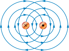
Parallel wires with currents in opposite directions repel, as you can see if we isolate the magnetic field lines of wire 2 influencing the current in wire 1. Right-hand rule 1 tells us the direction of the resulting magnetic force.

The two small circles with an x on the left and dot on the right representing wires with opposite currents are shown in this diagram. A blue arrow pointing down going through wire 1 is labeled Magnetic field due to wire 2. A red line from the center of wire 1 pointing to the left away from wire Wire 2 is labeled Magnetic force on wire 1 due to magnetic field of wire 2.
The same two wires with opposite currents are shown, but now only a part of the magnetic field due to wire 2 is shown in order to demonstrate how the magnetic force from wire 2 affects wire 1.

Questions & Answers

Ayele, K., 2003. Introductory Economics, 3rd ed., Addis Ababa.
Widad Reply
can you send the book attached ?
Ariel
?
Ariel
What is economics
Widad Reply
the study of how humans make choices under conditions of scarcity
AI-Robot
U(x,y) = (x×y)1/2 find mu of x for y
Desalegn Reply
U(x,y) = (x×y)1/2 find mu of x for y
Desalegn
what is ecnomics
Jan Reply
this is the study of how the society manages it's scarce resources
Belonwu
what is macroeconomic
John Reply
macroeconomic is the branch of economics which studies actions, scale, activities and behaviour of the aggregate economy as a whole.
husaini
etc
husaini
difference between firm and industry
husaini Reply
what's the difference between a firm and an industry
Abdul
firm is the unit which transform inputs to output where as industry contain combination of firms with similar production 😅😅
Abdulraufu
Suppose the demand function that a firm faces shifted from Qd  120 3P to Qd  90  3P and the supply function has shifted from QS  20  2P to QS 10  2P . a) Find the effect of this change on price and quantity. b) Which of the changes in demand and supply is higher?
Toofiq Reply
explain standard reason why economic is a science
innocent Reply
factors influencing supply
Petrus Reply
what is economic.
Milan Reply
scares means__________________ends resources. unlimited
Jan
economics is a science that studies human behaviour as a relationship b/w ends and scares means which have alternative uses
Jan
calculate the profit maximizing for demand and supply
Zarshad Reply
Why qualify 28 supplies
Milan
what are explicit costs
Nomsa Reply
out-of-pocket costs for a firm, for example, payments for wages and salaries, rent, or materials
AI-Robot
concepts of supply in microeconomics
David Reply
economic overview notes
Amahle Reply
identify a demand and a supply curve
Salome Reply
i don't know
Parul
there's a difference
Aryan
Demand curve shows that how supply and others conditions affect on demand of a particular thing and what percent demand increase whith increase of supply of goods
Israr
Hi Sir please how do u calculate Cross elastic demand and income elastic demand?
Abari
Got questions? Join the online conversation and get instant answers!
Jobilize.com Reply

Get Jobilize Job Search Mobile App in your pocket Now!

Get it on Google Play Download on the App Store Now


Source:  OpenStax, College physics for ap® courses. OpenStax CNX. Nov 04, 2016 Download for free at https://legacy.cnx.org/content/col11844/1.14
Google Play and the Google Play logo are trademarks of Google Inc.

Notification Switch

Would you like to follow the 'College physics for ap® courses' conversation and receive update notifications?

Ask