<< Chapter < Page Chapter >> Page >
The schematic shows a rectangular object on a background material. Two oscillatory waves go from left to right across the image. At the left of the image, the waves have the same wavelength and are in phase. The lower wave goes through the object, where its wavelength becomes significantly shorter. To the right of the object the waves again have the same wavelength but they are now almost completely out of phase.
Light rays passing through a sample under a microscope will emerge with different phases depending on their paths. The object shown has a greater index of refraction than the background, and so the wavelength decreases as the ray passes through it. Superimposing these rays produces interference that varies with path, enhancing contrast between the object and background.

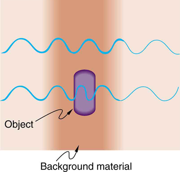
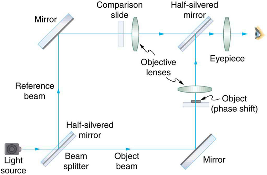
Interference microscopes enhance contrast between objects and background by superimposing a reference beam of light upon the light emerging from the sample. Since light from the background and objects differ in phase, there will be different amounts of constructive and destructive interference, producing the desired contrast in final intensity. [link] shows schematically how this is done. Parallel rays of light from a source are split into two beams by a half-silvered mirror. These beams are called the object and reference beams. Each beam passes through identical optical elements, except that the object beam passes through the object we wish to observe microscopically. The light beams are recombined by another half-silvered mirror and interfere. Since the light rays passing through different parts of the object have different phases, interference will be significantly different and, hence, have greater contrast between them.

The schematic shows an optical setup for an interference microscope. A light source produces a beam of light that is split into two beams by a beam splitter, which is a half silvered mirror. The beams are steered around the opposite side of a square and recombine at the corner diagonally opposite the beam splitter. The object being analyzed is placed in one arm so that the beam in that arm goes through the object.
An interference microscope utilizes interference between the reference and object beam to enhance contrast. The two beams are split by a half-silvered mirror; the object beam is sent through the object, and the reference beam is sent through otherwise identical optical elements. The beams are recombined by another half-silvered mirror, and the interference depends on the various phases emerging from different parts of the object, enhancing contrast.

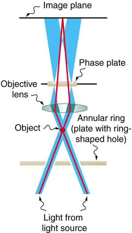
Another type of microscope utilizing wave interference and differences in phases to enhance contrast is called the phase-contrast microscope    . While its principle is the same as the interference microscope, the phase-contrast microscope is simpler to use and construct. Its impact (and the principle upon which it is based) was so important that its developer, the Dutch physicist Frits Zernike (1888–1966), was awarded the Nobel Prize in 1953. [link] shows the basic construction of a phase-contrast microscope. Phase differences between light passing through the object and background are produced by passing the rays through different parts of a phase plate (so called because it shifts the phase of the light passing through it). These two light rays are superimposed in the image plane, producing contrast due to their interference.

The schematic shows two beams of light going up from the bottom of the image and crossing at a point labeled object. After passing through the object, the beams diverge and then are focused by a convex lens. The light passes through a plate called the phase plate, and the beams then focus on the image plane. The background light diverges after passing through the phase plate so that it spreads away from the primary light beam on the image plane.
Simplified construction of a phase-contrast microscope. Phase differences between light passing through the object and background are produced by passing the rays through different parts of a phase plate. The light rays are superimposed in the image plane, producing contrast due to their interference.

A polarization microscope    also enhances contrast by utilizing a wave characteristic of light. Polarization microscopes are useful for objects that are optically active or birefringent, particularly if those characteristics vary from place to place in the object. Polarized light is sent through the object and then observed through a polarizing filter that is perpendicular to the original polarization direction. Nearly transparent objects can then appear with strong color and in high contrast. Many polarization effects are wavelength dependent, producing color in the processed image. Contrast results from the action of the polarizing filter in passing only components parallel to its axis.

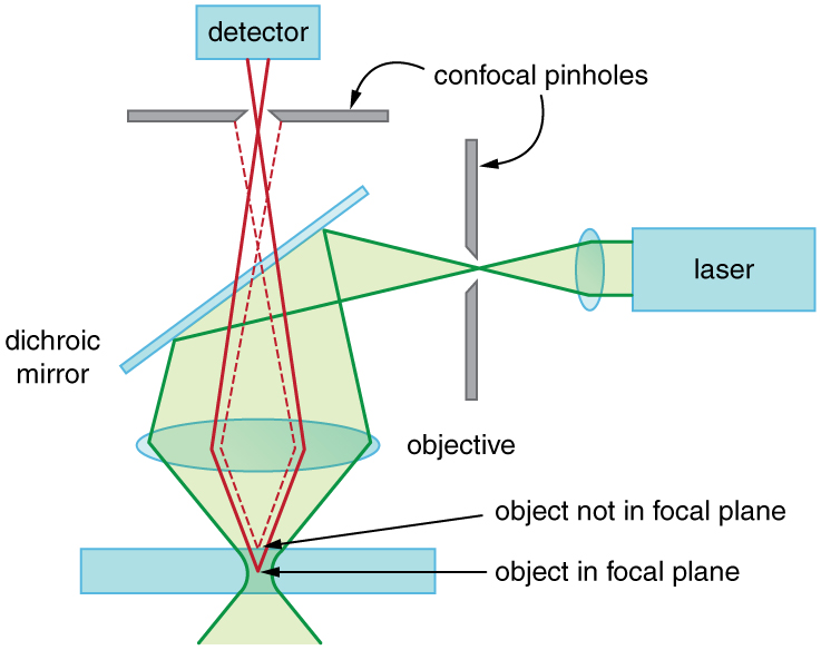
Apart from the UV microscope, the variations of microscopy discussed so far in this section are available as attachments to fairly standard microscopes or as slight variations. The next level of sophistication is provided by commercial confocal microscopes    , which use the extended focal region shown in [link] (b) to obtain three-dimensional images rather than two-dimensional images. Here, only a single plane or region of focus is identified; out-of-focus regions above and below this plane are subtracted out by a computer so the image quality is much better. This type of microscope makes use of fluorescence, where a laser provides the excitation light. Laser light passing through a tiny aperture called a pinhole forms an extended focal region within the specimen. The reflected light passes through the objective lens to a second pinhole and the photomultiplier detector, see [link] . The second pinhole is the key here and serves to block much of the light from points that are not at the focal point of the objective lens. The pinhole is conjugate (coupled) to the focal point of the lens. The second pinhole and detector are scanned, allowing reflected light from a small region or section of the extended focal region to be imaged at any one time. The out-of-focus light is excluded. Each image is stored in a computer, and a full scanned image is generated in a short time. Live cell processes can also be imaged at adequate scanning speeds allowing the imaging of three-dimensional microscopic movement. Confocal microscopy enhances images over conventional optical microscopy, especially for thicker specimens, and so has become quite popular.

The next level of sophistication is provided by microscopes attached to instruments that isolate and detect only a small wavelength band of light—monochromators and spectral analyzers. Here, the monochromatic light from a laser is scattered from the specimen. This scattered light shifts up or down as it excites particular energy levels in the sample. The uniqueness of the observed scattered light can give detailed information about the chemical composition of a given spot on the sample with high contrast—like molecular fingerprints. Applications are in materials science, nanotechnology, and the biomedical field. Fine details in biochemical processes over time can even be detected. The ultimate in microscopy is the electron microscope—to be discussed later. Research is being conducted into the development of new prototype microscopes that can become commercially available, providing better diagnostic and research capacities.

Schematic of a confocal microscope. There is a sample at the bottom, a pinhole at the top, and a pinhole at the right side. The sample is a horizontal rectangle that is rather thick in the vertical direction. A green laser beam coming from the right is focused through the right pinhole, then reflects downward off of a dichroic mirror. It is then collected by a horizontal objective lens and focused onto the sample. The focus is not a point, but an extended zone where the beam diameter is minimal. Two solid red rays leave the focal plane of the objective lens and diverge upward. This plane is inside the sample and is labeled object in focal plane. These rays pass through the objective lens and begin to converge. After passing through the dichroic mirror, they continue upward and are focused through the top pinhole. After passing through this pinhole, these rays enter a detector. Two dashed red rays leave the sample at a point slightly above the focal plane, which is labeled object not in focal plane. These rays follow similar paths as the solid red rays, but they do not focus on the pinhole and so are blocked and do not reach the detector.
A confocal microscope provides three-dimensional images using pinholes and the extended depth of focus as described by wave optics. The right pinhole illuminates a tiny region of the sample in the focal plane. In-focus light rays from this tiny region pass through the dichroic mirror and the second pinhole to a detector and a computer. Out-of-focus light rays are blocked. The pinhole is scanned sideways to form an image of the entire focal plane. The pinhole can then be scanned up and down to gather images from different focal planes. The result is a three-dimensional image of the specimen.

Section summary

  • To improve microscope images, various techniques utilizing the wave characteristics of light have been developed. Many of these enhance contrast with interference effects.

Conceptual questions

Explain how microscopes can use wave optics to improve contrast and why this is important.

Got questions? Get instant answers now!

A bright white light under water is collimated and directed upon a prism. What range of colors does one see emerging?

Got questions? Get instant answers now!

Questions & Answers

Three charges q_{1}=+3\mu C, q_{2}=+6\mu C and q_{3}=+8\mu C are located at (2,0)m (0,0)m and (0,3) coordinates respectively. Find the magnitude and direction acted upon q_{2} by the two other charges.Draw the correct graphical illustration of the problem above showing the direction of all forces.
Kate Reply
To solve this problem, we need to first find the net force acting on charge q_{2}. The magnitude of the force exerted by q_{1} on q_{2} is given by F=\frac{kq_{1}q_{2}}{r^{2}} where k is the Coulomb constant, q_{1} and q_{2} are the charges of the particles, and r is the distance between them.
Muhammed
What is the direction and net electric force on q_{1}= 5µC located at (0,4)r due to charges q_{2}=7mu located at (0,0)m and q_{3}=3\mu C located at (4,0)m?
Kate Reply
what is the change in momentum of a body?
Eunice Reply
what is a capacitor?
Raymond Reply
Capacitor is a separation of opposite charges using an insulator of very small dimension between them. Capacitor is used for allowing an AC (alternating current) to pass while a DC (direct current) is blocked.
Gautam
A motor travelling at 72km/m on sighting a stop sign applying the breaks such that under constant deaccelerate in the meters of 50 metres what is the magnitude of the accelerate
Maria Reply
please solve
Sharon
8m/s²
Aishat
What is Thermodynamics
Muordit
velocity can be 72 km/h in question. 72 km/h=20 m/s, v^2=2.a.x , 20^2=2.a.50, a=4 m/s^2.
Mehmet
A boat travels due east at a speed of 40meter per seconds across a river flowing due south at 30meter per seconds. what is the resultant speed of the boat
Saheed Reply
50 m/s due south east
Someone
which has a higher temperature, 1cup of boiling water or 1teapot of boiling water which can transfer more heat 1cup of boiling water or 1 teapot of boiling water explain your . answer
Ramon Reply
I believe temperature being an intensive property does not change for any amount of boiling water whereas heat being an extensive property changes with amount/size of the system.
Someone
Scratch that
Someone
temperature for any amount of water to boil at ntp is 100⁰C (it is a state function and and intensive property) and it depends both will give same amount of heat because the surface available for heat transfer is greater in case of the kettle as well as the heat stored in it but if you talk.....
Someone
about the amount of heat stored in the system then in that case since the mass of water in the kettle is greater so more energy is required to raise the temperature b/c more molecules of water are present in the kettle
Someone
definitely of physics
Haryormhidey Reply
how many start and codon
Esrael Reply
what is field
Felix Reply
physics, biology and chemistry this is my Field
ALIYU
field is a region of space under the influence of some physical properties
Collete
what is ogarnic chemistry
WISDOM Reply
determine the slope giving that 3y+ 2x-14=0
WISDOM
Another formula for Acceleration
Belty Reply
a=v/t. a=f/m a
IHUMA
innocent
Adah
pratica A on solution of hydro chloric acid,B is a solution containing 0.5000 mole ofsodium chlorid per dm³,put A in the burret and titrate 20.00 or 25.00cm³ portion of B using melting orange as the indicator. record the deside of your burret tabulate the burret reading and calculate the average volume of acid used?
Nassze Reply
how do lnternal energy measures
Esrael
Two bodies attract each other electrically. Do they both have to be charged? Answer the same question if the bodies repel one another.
JALLAH Reply
No. According to Isac Newtons law. this two bodies maybe you and the wall beside you. Attracting depends on the mass och each body and distance between them.
Dlovan
Are you really asking if two bodies have to be charged to be influenced by Coulombs Law?
Robert
like charges repel while unlike charges atttact
Raymond
What is specific heat capacity
Destiny Reply
Specific heat capacity is a measure of the amount of energy required to raise the temperature of a substance by one degree Celsius (or Kelvin). It is measured in Joules per kilogram per degree Celsius (J/kg°C).
AI-Robot
specific heat capacity is the amount of energy needed to raise the temperature of a substance by one degree Celsius or kelvin
ROKEEB
Got questions? Join the online conversation and get instant answers!
Jobilize.com Reply
Practice Key Terms 6

Get Jobilize Job Search Mobile App in your pocket Now!

Get it on Google Play Download on the App Store Now


Source:  OpenStax, College physics for ap® courses. OpenStax CNX. Nov 04, 2016 Download for free at https://legacy.cnx.org/content/col11844/1.14
Google Play and the Google Play logo are trademarks of Google Inc.

Notification Switch

Would you like to follow the 'College physics for ap® courses' conversation and receive update notifications?

Ask