

| << Chapter < Page | Chapter >> Page > |
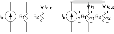
One interesting simple circuit ( [link] ) has two resistors connected side-by-side, what we will term a parallel connection, rather than in series. Here, applying KVL reveals that all the voltages are identical: and . This result typifies parallel connections. To write the KCLequation, note that the top node consists of the entire upper interconnection section. The KCL equation is . Using the v-i relations, we find that
Suppose that you replaced the current source in [link] by a voltage source. How would be related to the source voltage? Based on this result, what purpose does this revised circuit have?
Replacing the current source by a voltage source does not change the fact that the voltages areidentical. Consequently, or . This result does not depend on the resistor , which means that we simply have a resistor( ) across a voltage source. The two-resistor circuit has noapparent use.
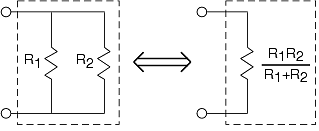
This circuit highlights some important properties of parallel circuits. You can easily show that the parallel combination of and has the v-i relation of a resistor having resistance . A shorthand notation for this quantity is . As the reciprocal of resistance is conductance , we can say that for a parallel combination of resistors, the equivalent conductance is the sum of the conductances .
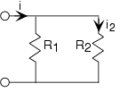
Similar to voltage divider for series resistances, we have current divider for parallel resistances. The current through a resistor in parallel with another is the ratio of theconductance of the first to the sum of the conductances. Thus, for the depicted circuit, . Expressed in terms of resistances, current divider takes the form of the resistance of the other resistor divided by the sum of resistances: .
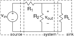
Suppose we want to pass the output signal into a voltage measurement device, such as an oscilloscope or a voltmeter. Insystem-theory terms, we want to pass our circuit's output to a sink. For most applications, we can represent these measurementdevices as a resistor, with the current passing through it driving the measurement device through some type of display.In circuits, a sink is called a load ; thus, we describe a system-theoretic sink as a load resistance . Thus, we have a complete system built from a cascade of threesystems: a source, a signal processing system (simple as it is), and a sink.
We must analyze afresh how this revised circuit, shown in [link] , works. Rather than defining eight variables and solving for thecurrent in the load resistor, let's take a hint from other analysis( series rules , parallel rules ). Resistors and are in a parallel configuration: The voltages across each resistor are the same while the currents arenot. Because the voltages are the same, we can find the current through each from their v-i relations: and . Considering the node where all three resistors join, KCL saysthat the sum of the three currents must equal zero. Said another way, the current entering the node through must equal the sum of the other two currents leaving the node. Therefore, , which means that .
Notification Switch
Would you like to follow the 'Circuits' conversation and receive update notifications?

|
|

|
|

|
|

|
|
|
|
|

|
|

|
|
|
|
|

|
|

|