<< Chapter < Page Chapter >> Page >

Learning objectives

By the end of this section, you will be able to:

  • Describe how motors and meters work in terms of torque on a current loop.
  • Calculate the torque on a current-carrying loop in a magnetic field.

Motors are the most common application of magnetic force on current-carrying wires. Motors have loops of wire in a magnetic field. When current is passed through the loops, the magnetic field exerts torque on the loops, which rotates a shaft. Electrical energy is converted to mechanical work in the process. (See [link] .)
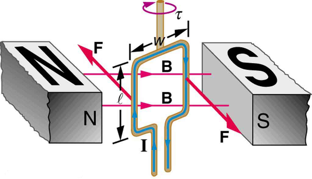
Diagram showing a current-carrying loop of width w and length l between the north and south poles of a magnet. The north pole is to the left and the south pole is to the right of the loop. The magnetic field B runs from the north pole across the loop to the south pole. The loop is shown at an instant, while rotating clockwise. The current runs up the left side of the loop, across the top, and down the right side. There is a force F oriented into the page on the left side of the loop and a force F oriented out of the page on the right side of the loop. The torque on the loop is clockwise as viewed from above.
Torque on a current loop. A current-carrying loop of wire attached to a vertically rotating shaft feels magnetic forces that produce a clockwise torque as viewed from above.

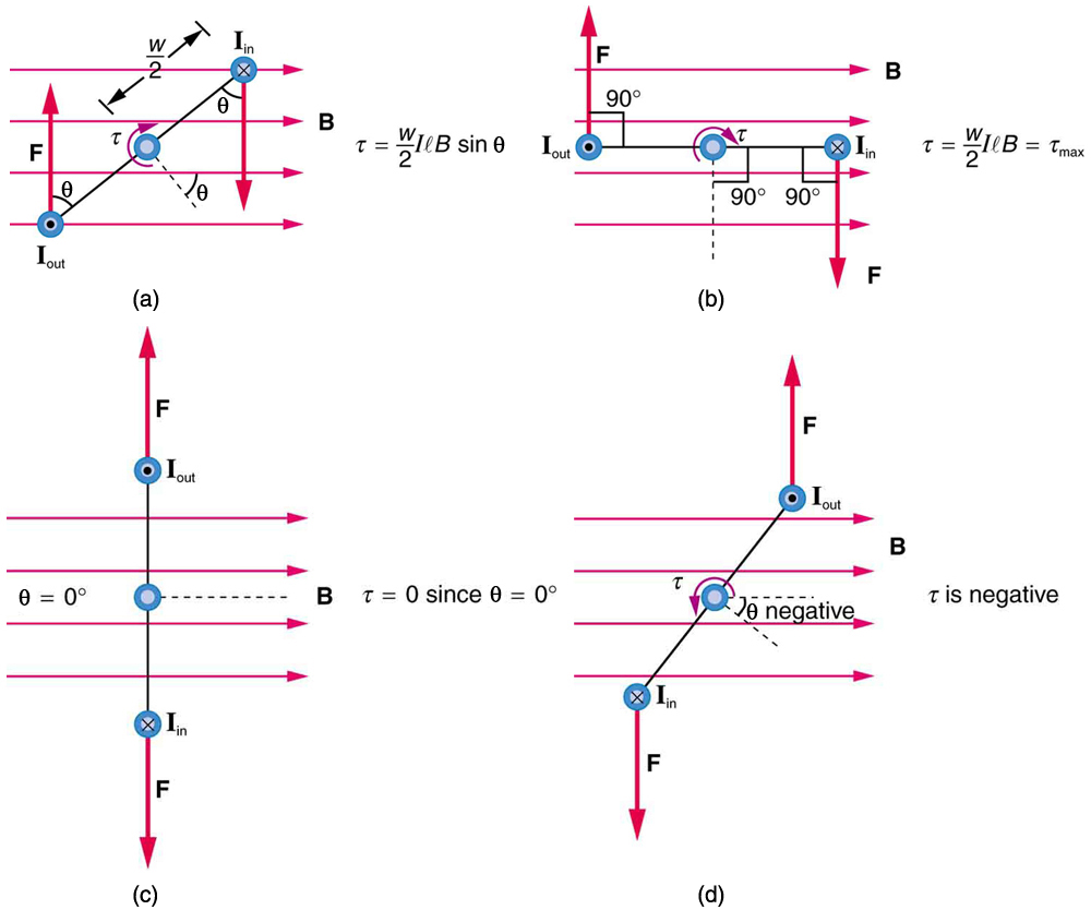
Let us examine the force on each segment of the loop in [link] to find the torques produced about the axis of the vertical shaft. (This will lead to a useful equation for the torque on the loop.) We take the magnetic field to be uniform over the rectangular loop, which has width w and height l . First, we note that the forces on the top and bottom segments are vertical and, therefore, parallel to the shaft, producing no torque. Those vertical forces are equal in magnitude and opposite in direction, so that they also produce no net force on the loop. [link] shows views of the loop from above. Torque is defined as τ = rF sin θ size 12{τ= ital "rF""sin"θ} {} , where F size 12{F} {} is the force, r is the distance from the pivot that the force is applied, and θ is the angle between r and F . As seen in [link] (a), right hand rule 1 gives the forces on the sides to be equal in magnitude and opposite in direction, so that the net force is again zero. However, each force produces a clockwise torque. Since r = w / 2 , the torque on each vertical segment is ( w / 2 ) F sin θ , and the two add to give a total torque.
τ = w 2 F sin θ + w 2 F sin θ = wF sin θ size 12{τ= { {w} over {2} } F"sin"θ+ { {w} over {2} } F"sin"θ= ital "wF""sin"θ} {}
Diagram showing a current-carrying loop from the top, and four different times as it rotates in a magnetic field. The magnetic field oriented toward the right, perpendicular to the vertical dimension of the loop. In figure a, the top view of the loop is oriented at an angle to the magnetic field lines, which run left to right. The force on the loop is up on the lower left side where the current comes out of the page. The force is down on the upper right side where the loop goes into the page. The angle between the force and the loop is theta. Torque is clockwise and equals w over 2 times I l B sine theta. Figure b shows the top view of the loop parallel to the magnetic field lines. The force on the loop is up on the left side where I comes out of the page. The force on the loop is down on the right side where I goes into the page. The angle theta between the F and B is ninety degrees. Torque is clockwise and equals w over 2 I l B equals maximum torque. Figure c shows the top view of the loop oriented perpendicular to B. The force on the loop is up at the top, where I comes out of the page, and down at the bottom where I goes into the page. Theta equals 0 degrees. Torque equals zero since sine theta equals 0. In figure d the force is down on the lower left side of the loop where I goes in, and up on the upper right side of the loop where I comes out. The torque is counterclockwise. Torque is negative.
Top views of a current-carrying loop in a magnetic field. (a) The equation for torque is derived using this view. Note that the perpendicular to the loop makes an angle θ size 12{θ} {} with the field that is the same as the angle between w / 2 size 12{w/2} {} and F size 12{F} {} . (b) The maximum torque occurs when θ size 12{θ} {} is a right angle and sin θ = 1 size 12{"sin"θ=1} {} . (c) Zero (minimum) torque occurs when θ size 12{θ} {} is zero and sin θ = 0 . (d) The torque reverses once the loop rotates past θ = 0 .

Now, each vertical segment has a length l size 12{l} {} that is perpendicular to B size 12{B} {} , so that the force on each is F = IlB size 12{F= ital "IlB"} {} . Entering F size 12{F} {} into the expression for torque yields

τ = wIlB sin θ . size 12{τ= ital "wIlB""sin"θ} {}

If we have a multiple loop of N size 12{N} {} turns, we get N size 12{N} {} times the torque of one loop. Finally, note that the area of the loop is A = wl size 12{A= ital "wl"} {} ; the expression for the torque becomes

τ = NIAB sin θ . size 12{τ= ital "NIAB""sin"θ} {}

This is the torque on a current-carrying loop in a uniform magnetic field. This equation can be shown to be valid for a loop of any shape. The loop carries a current I size 12{I} {} , has N size 12{N} {} turns, each of area A size 12{A} {} , and the perpendicular to the loop makes an angle θ size 12{θ} {} with the field B size 12{B} {} . The net force on the loop is zero.

Calculating torque on a current-carrying loop in a strong magnetic field

Find the maximum torque on a 100-turn square loop of a wire of 10.0 cm on a side that carries 15.0 A of current in a 2.00-T field.

Strategy

Torque on the loop can be found using τ = NIAB sin θ size 12{τ= ital "NIAB""sin"θ} {} . Maximum torque occurs when θ = 90º and sin θ = 1 size 12{"sin"θ=1} {} .

Solution

For sin θ = 1 size 12{"sin"θ=1} {} , the maximum torque is

τ max = NIAB . size 12{τ rSub { size 8{"max"} } = ital "NIAB"} {}

Entering known values yields

τ max = 100 15.0 A 0.100 m 2 2 . 00 T = 30.0 N m. alignl { stack { size 12{τ rSub { size 8{"max"} } = left ("100" right ) left ("15" "." 0" A" right ) left (0 "." "100"" m" rSup { size 8{2} } right ) left (2 "." "00"" T" right )} {} #" "="30" "." "0 N" cdot m "." {} } } {}

Discussion

This torque is large enough to be useful in a motor.

Got questions? Get instant answers now!
Practice Key Terms 2

Get Jobilize Job Search Mobile App in your pocket Now!

Get it on Google Play Download on the App Store Now


Source:  OpenStax, College physics for ap® courses. OpenStax CNX. Nov 04, 2016 Download for free at https://legacy.cnx.org/content/col11844/1.14
Google Play and the Google Play logo are trademarks of Google Inc.

Notification Switch

Would you like to follow the 'College physics for ap® courses' conversation and receive update notifications?

Ask