<< Chapter < Page Chapter >> Page >

Learning objectives

By the end of this section, you will be able to:

  • Describe the effects of a magnetic force on a current-carrying conductor.
  • Calculate the magnetic force on a current-carrying conductor.

The information presented in this section supports the following AP® learning objectives and science practices:

  • 3.C.3.1 The student is able to use right-hand rules to analyze a situation involving a current-carrying conductor and a moving electrically charged object to determine the direction of the magnetic force exerted on the charged object due to the magnetic field created by the current-carrying conductor. (S.P. 1.4)

Because charges ordinarily cannot escape a conductor, the magnetic force on charges moving in a conductor is transmitted to the conductor itself.

A diagram showing a circuit with current I running through it. One section of the wire passes between the north and south poles of a magnet with a diameter l. Magnetic field B is oriented toward the right, from the north to the south pole of the magnet, across the wire. The current runs out of the page. The force on the wire is directed up. An illustration of the right hand rule 1 shows the thumb pointing out of the page in the direction of the current, the fingers pointing right in the direction of B, and the F vector pointing up and away from the palm.
The magnetic field exerts a force on a current-carrying wire in a direction given by the right hand rule 1 (the same direction as that on the individual moving charges). This force can easily be large enough to move the wire, since typical currents consist of very large numbers of moving charges.

We can derive an expression for the magnetic force on a current by taking a sum of the magnetic forces on individual charges. (The forces add because they are in the same direction.) The force on an individual charge moving at the drift velocity v d is given by F = qv d B sin θ . Taking B size 12{B} {} to be uniform over a length of wire l and zero elsewhere, the total magnetic force on the wire is then F = ( qv d B sin θ ) ( N ) size 12{F= \( ital "qv" rSub { size 8{d} } B"sin"θ \) \( N \) } {} , where N size 12{N} {} is the number of charge carriers in the section of wire of length l size 12{l} {} . Now, N = nV size 12{N= ital "nV"} {} , where n size 12{n} {} is the number of charge carriers per unit volume and V size 12{V} {} is the volume of wire in the field. Noting that V = Al size 12{V= ital "Al"} {} , where A size 12{A} {} is the cross-sectional area of the wire, then the force on the wire is F = ( qv d B sin θ ) ( nAl ) . Gathering terms,

F = ( nqAv d ) lB sin θ . size 12{F= \( ital "nqAv" rSub { size 8{d} } \) ital "lB""sin"θ} {}

Because nqAv d = I size 12{ ital "nqAv" rSub { size 8{d} } =I} {} (see Current ),

F = IlB sin θ size 12{F= ital "IlB""sin"θ} {}

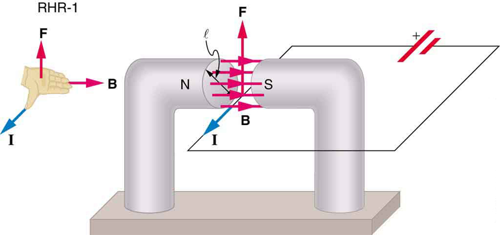
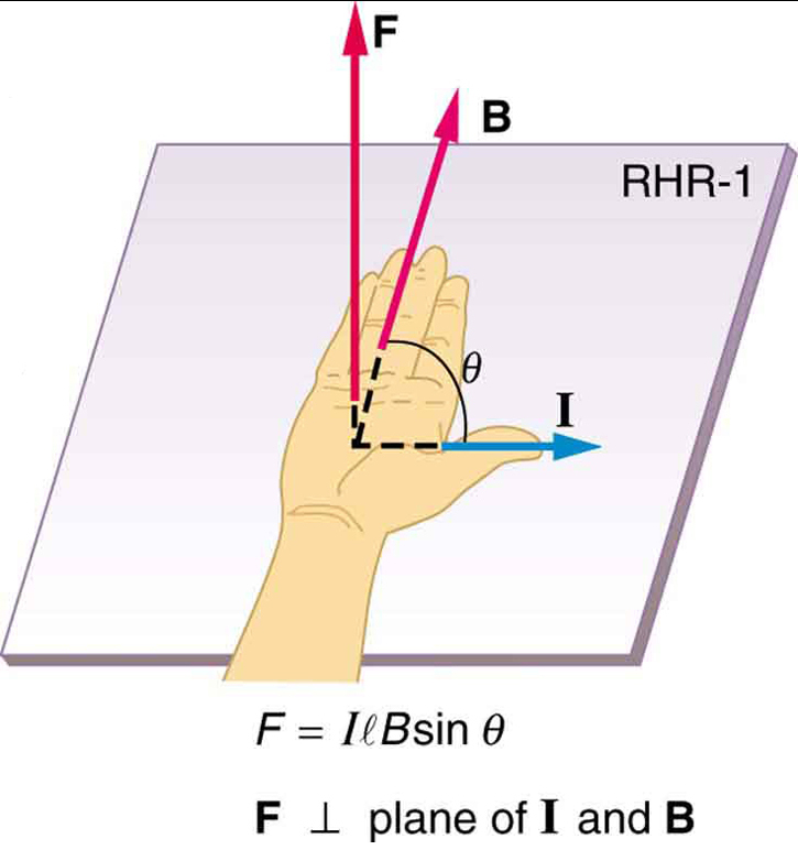
is the equation for magnetic force on a length l of wire carrying a current I in a uniform magnetic field B , as shown in [link] . If we divide both sides of this expression by l , we find that the magnetic force per unit length of wire in a uniform field is F l = IB sin θ size 12{ { {F} over {l} } = ital "IB""sin"θ} {} . The direction of this force is given by RHR-1, with the thumb in the direction of the current I size 12{I} {} . Then, with the fingers in the direction of B size 12{B} {} , a perpendicular to the palm points in the direction of F size 12{F} {} , as in [link] .

Illustration of the right hand rule 1 showing the thumb pointing right in the direction of current I, the fingers pointing into the page with magnetic field B, and the force directed up, away from the palm.
The force on a current-carrying wire in a magnetic field is F = IlB sin θ size 12{F= ital "IlB""sin"θ} {} . Its direction is given by RHR-1.

Calculating magnetic force on a current-carrying wire: a strong magnetic field

Calculate the force on the wire shown in [link] , given B = 1 . 50 T size 12{B=1 "." "50"" T"} {} , l = 5 . 00 cm size 12{l=5 "." "00"" cm"} {} , and I = 20 . 0 A size 12{I="20" "." 0 A} {} .

Strategy

The force can be found with the given information by using F = IlB sin θ size 12{F= ital "IlB""sin"θ} {} and noting that the angle θ size 12{θ} {} between I size 12{I} {} and B size 12{B} {} is 90º , so that sin θ = 1 .

Solution

Entering the given values into F = IlB sin θ size 12{F= ital "IlB""sin"θ} {} yields

F = IlB sin θ = 20 .0 A 0 . 0500 m 1 . 50 T 1 . size 12{F= ital "IlB""sin"θ= left ("20" "." 0" A" right ) left (0 "." "0500"" m" right ) left (1 "." "50"" T" right ) left (1 right )} {}

The units for tesla are 1 T = N A m size 12{"1 T"= { {N} over {A cdot m} } } {} ; thus,

F = 1 . 50 N. size 12{F=1 "." "50"" N"} {}

Discussion

This large magnetic field creates a significant force on a small length of wire.

Got questions? Get instant answers now!

Magnetic force on current-carrying conductors is used to convert electric energy to work. (Motors are a prime example—they employ loops of wire and are considered in the next section.) Magnetohydrodynamics (MHD) is the technical name given to a clever application where magnetic force pumps fluids without moving mechanical parts. (See [link] .)

Get Jobilize Job Search Mobile App in your pocket Now!

Get it on Google Play Download on the App Store Now


Source:  OpenStax, College physics for ap® courses. OpenStax CNX. Nov 04, 2016 Download for free at https://legacy.cnx.org/content/col11844/1.14
Google Play and the Google Play logo are trademarks of Google Inc.

Notification Switch

Would you like to follow the 'College physics for ap® courses' conversation and receive update notifications?

Ask